
H-RADIO software for
ATS25 / ATS120 receiver
version 4.16 AIR / 23.07.2023
|
The latest software shell for receivers ATS25, ATS25+, ATS25X1, ATS25X2, ATS25 max, ATS120 and ATS25 max-Decoder based on a microcontroller ESP32 with color touch screen and radio on chip SI4732 / SI4735 Video overview of the firmware H-RADIO for the receiver ATS25 / ATS120 |
 |
 |
 |
 |
 |
 |
| Scanning of the range | Style retro | Screen rotation | Regional settings | Radio amateur functions | Station memory |
 |
 |
 |
 |
 |
 |
| Device setup | Network functions | Keyboard | RDS functions | CB range | Versions for all modifications |
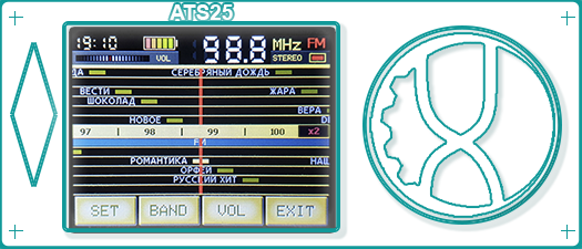
A wide range of tools for searching for working stations is available in the firmware. The scanning of the selected range is implemented with the display as a graph with the frequency on the X axis and the RSSI signal level on the Y axis. On the graph, the frequencies at which the carrier signal of radio stations is detected are highlighted in color. It is possible to scale the graph by frequency and by signal level. Adjusting the contrast of the graph allows you to see even the weakest carrier frequency signal. If necessary, you can fit the entire range into the receiver screen with a single tap. The cursor of the current listening frequency can be set at any position of the graph, while the signal level changing in real time will be displayed for the selected frequency. By moving the cursor, you can shift the graph by frequency to the left or right. The graph shows the end and start frequencies, grid pitch, scale, and current values of RSSI and SNR levels at the cursor position. If there are specified boundaries of frequency sections for the selected range in the label.csv file, then these sections will be displayed on the graph. Thanks to this tool, you can easily and quickly find working stations and assess the air traffic in amateur radio bands in areas of various permitted types of radio communication. There is a tool for searching radio stations up or down in frequency. The search algorithm excludes missing stations or false stops where there is no carrier frequency. Another useful tool will be an FM band scanner to create a list of broadcast radio stations in your region. Just one click and the receiver will automatically scan the entire FM band and offer to save the found stations to memory. Then you can change the names of the stations in memory. |
|||||
 |
 |
 |
|||
The firmware presents an interface in the retro style of the receiver. The retro scale displays the stations stored in memory, as well as the frequency scale. If there are specified boundaries of frequency sections for the selected range in the label file label.csv, then these sections will be displayed on the scale. Scaling of the scale is possible. In the version for the receiver with a large HVGA format screen, the S-meter is displayed on the retro scale in the form of a pointer device. It is possible to select a range from the list that is presented as it was in retro receivers. The short wave ranges are divided by time of day with the best conditions for reception. If the receiver is connected to the Internet, information about the passage of radio waves on HF is displayed in the list of bands. For each location where you use the receiver, you can create your own retro scale with a list of stations. Move the retro scale with the encoder or swipe the screen. |
|||||
 |
 |
 |
|||
Rotate the screen as you like. Do this in the settings menu or at any time using a combination of actions. At the same time, the position will remain for the start screen. So you can make your receiver with a convenient arrangement of controls and screen. |
|||||
The interface is translated into various languages. Localization files are supplied with the firmware and can be downloaded to the receiver at your request. It is possible to create a custom localization file. The firmware supports ITU regional standards, such as band boundaries and frequency tuning pitch. The FM band can start at 64 MHz or 87.5 MHz. For RDS, it is possible to enable the display of the program type in the RBDS standard for North America. The watch supports 12- and 24-hour standards. And in the firmware for the HVGA format screen, along with the RDS information, the country flag for the selected interface language is displayed. |
|||||
 |
 |
 |
|||
The firmware contains a number of convenient functions for radio amateurs. Amateur radio bands are collected in a single list. By default, the range boundaries are set according to the ITU standard. At your discretion, you can change the range boundaries in the setting.ini file. It is possible to set a minimum frequency up to 132 kHz to receive signals from weather services, navigation and control systems, and accurate time signals. Amateur radio bands use SSB modulation and different bandwidth to receive voice transmissions, telegraph and digital signals. Synchronous reception with the upper or lower sideband in broadcast bands is possible. The firmware uses two VF's to quickly switch between the set range settings, frequency, type of modulation, tuning step, bandwidth and BFO settings. To switch between the VFO, just click on the frequency indicator. The tuning accuracy in SSB mode can be changed up to 10 Hz. Click on the corresponding segment of the frequency indicator to select the accuracy of the setting. A built-in BFO generator is used to fine tune the signal of an amateur station. The calibrated S-meter allows you to estimate the level of the received signal. For a receiver with an HVGA display, a waterfall indicator is available showing the change in signal strength over time. Use AGC or built-in attenuator to improve reception quality. For a receiver with a built-in CW decoder and digital communication types, decoded signals can be displayed on the receiver screen. The list of supported digital protocols is constantly updated. For the convenience of tuning to the decoded signal, you can use an audio spectrum analyzer in the form of a "waterfall" or a histogram. If the circuit of your receiver contains an antenna switch, then its operation can be automated by configuring the switching circuit. Or switch the antenna manually in the range lists or settings menu. The latest receiver model ATS25 max-Decoder already contains the necessary schematics to support all firmware functions. There is a special section that contains information about the current state of all receiver settings and the conditions for passing waves on short waves. |
|||||
 |
 |
 |
|||
Create your own list of stations. The number of memory cells is unlimited. You can create your own list of stations for each location. Each station can be linked to a location or allowed to be used for all locations. For each cell, the name, frequency, range, type of modulation and location binding are stored. The station name can be of any length and is not necessarily unique. The name and location binding can be edited. Unnecessary stations can be deleted. There is a filter in the list of stations to display stations only from the current range or received at the current location. All stations and locations are saved to files in the receiver's internal memory and can be saved to a computer and, if necessary, edited and copied back to the receiver. This allows you to quickly create your station lists and share them. |
|||||
 |
 |
 |
|||
The firmware allows you to configure the operation of the receiver according to your needs. Flexible interface configuration allows you to change the appearance, enable and disable individual elements. There is an opportunity to upload a unique package of interface button images to the receiver. Depending on the presence of individual circuit elements in your receiver, it is possible to enable or disable support for these elements in the firmware. Set up your connection to a Wi-Fi hotspot. The list of saved access points can be edited. The list is stored in a file in the receiver's internal memory and can be copied to a computer. Passwords are stored encrypted. The settings menu allows you to flexibly configure the range scanner, the memory list, and turning off the display when there are no actions for a long time. Using a special settings file setting.ini, you can configure the search parameters for stations or an internal Wi-Fi access point, optimize the display of battery status and enable various debugging modes. The settings menu contains an item to reset the receiver to its original state. At startup, it is possible to calibrate the screen sensor and stop the download for preliminary modification of files inside the receiver using a computer. Changing the firmware settings is safe, when turned on, you can reset the settings if they do not allow the receiver to boot correctly. |
|||||
 |
 |
 |
|||
Using the built-in Wi-Fi module adds a number of useful features. Displaying the exact time for your location on the receiver display, information about the passage of waves on the HF bands, information about the availability of a new firmware version. Connecting the receiver to a Wi-Fi access point with the built-in web server files allows you to control all the functions of the receiver using a computer or mobile device via a browser. If you use remote control over the Internet, the watchdog timer will monitor the connection and restore it if necessary. Information about the current Wi-Fi connection is displayed on the info page and in the settings menu. An Internet connection can be used to activate the firmware or revoke the license key to bind it to another device. |
|||||
 |
 |
 |
|||
The touch screen allows you to use a full-fledged keyboard to enter station names or locations, Wi-Fi passwords and to activate the firmware. The keyboard contains the necessary set of characters for each function. Including Cyrillic layout, lowercase and uppercase letters and the standard ASCII character set. It is possible to delete the entered characters and set the cursor to any position. The updated activation algorithm allows you to eliminate input errors. The firmware contains a special error handling algorithm when the encoder is running with severe wear, however, if the encoder is not working well or you do not want to use it, there is a replacement in the form of an on-screen encoder, which can be called by swiping from the bottom of the screen up in any receiver mode. |
|||||
The main RDS functions are supported: station name, program type, RDS text, exact time and date. The type of program can be displayed in a generally accepted standard or in the RBDS standard used in the United States. The exact time signals are used to set the receiver's clock if there is no internet connection. The RDS text and the name of the station are displayed in various modes of operation of the receiver as a running line. If the RDS information is displayed incorrectly due to poor FM signal quality, it is possible to disable the RDS functions. A special algorithm determines the signal quality and can disable RDS reception automatically until the signal improves. |
|||||
 |
 |
 |
|||
Entering the CB band reception mode allows you to switch channels of standard civil band grids. Switching grids and the type of modulation is performed by clicking on the corresponding indicator. The firmware for the HVGA screen uses buttons on the screen. It is possible to receive transmissions with LSB and USB modulation with fine-tuning of BFO. The grid is supported both with zeros at the end of the frequency and with fives. All possible grids of the CB range are used. The firmware has a similar function for the FM band. Enabling this feature provides the convenience of navigating through saved FM stations for your location. In this mode, RDS information is also displayed if this option is enabled. For the convenience of listening, use a noise canceller. The noise canceller is adjusted together with the volume control. To switch, press the volume level display during adjustment. |
|||||
 |
 |
 |
|||
Despite the fact that the firmware is designed for mass-produced ATS25 receivers, it is possible to use it on homemade devices with various modifications of the circuit. Modifications using a large HVGA format screen on an ILI9488 chip are supported. It is possible to replace the reference frequency generator with a SI5351 chip. On the firmware files page, you need to download the installation package corresponding to the configuration of your device. On our forum you will find schemes of receiver improvements supported by the latest firmware version. Use the setting.ini file to make changes to the firmware according to your configuration. You can adjust the controller pins used, the operation of the automatic antenna switch and adjust the directions of the screen sensor. The encoder in your receiver may require firmware settings. In the settings, correct the direction of rotation and the pitch of the encoder if it does not work correctly. |
|||||
 |
|||||
Thanks to the wide customization and firmware management capabilities of the device, a base has been created for further improvement of the receiver functions both on the basis of the already existing simple scheme, and with the possibility of supplementing the functionality by making schematic changes. Information about the latest modifications of the receiver is available on forum. The way is open for users to create their own firmware customization packages (station lists for different regions, localization files, layouts for the built-in web server and button files for interface customization) for personal or public use. All information about the additions can be found on our forum and download page. The software product will continue to be improved based on the wishes of users of amateur radio equipment and to support innovations in the receiver circuit. |
|||||